मोटार अभ्यासणे
मोटार खोलताना लागणारे
टूल्स :- १. टेस्टर २. स्पॅनर ३. हॅमर ४. लाकडी ठोकला ५. मल्टिमीट
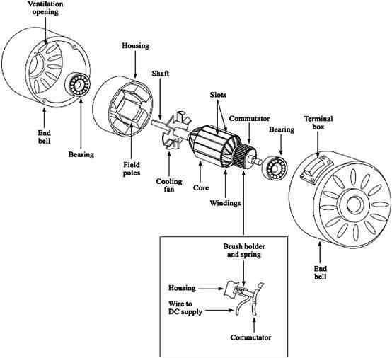
* मोटारचे पार्ट :- १. बेरिंग २. कॅप्यासीटर ३. बेरिंग कॅप ४. रोटर ५. फॅन ६. कोइल ७. स्लॉट
८. कव्हर बॉडी ९. बुश १०. कनेक्शन प्लेट ११. इम्पेलर १२. फूटबॉल
* १ एच पी मोटर खोलली :-
आलेली अडचन :- मोटारचा इम्पेलर घासत होता. पाणी लिक होत होते.
केलेले उपाय :- इम्पेलर ला रबरी प्याकिंग टाकली. त्यामुळे पाणी लिक होण्
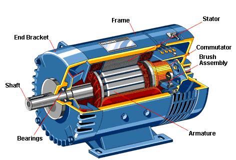
Electrical Siphon Motor Parts
[1]:-Coil
[2]:-Roatar
[3]:-Bush bajling
[4]:-Empalas
[5]:-Capacitor
Sr.no matwalu rate cont tolal
[1]:- buttan 15 1 15
Electrica Starter
* We leatnt about a sfarter
* We leatnt about a sfarter
* A stafer is a mechanical or an antomatic derice which helps the motor start
* A starter uses a on volt coil to create a magnetic field and join the contactors
* A sfartors has :-(1) contocfors thermcd control switeh piunger
* plunges :- Contains a no volt coil when given a current becomel a mageet and joins the contacteri rogether
* Contacters :- Pices of copper which connect to the main supply
* Thermal contail switch :-Contains a bi-metal strip which on reaching a desired current bends and disconnects from the maj supply.
*A motor starter uses 2 phases to work
Electcal
* Pipc type earthing :- 500mm × 500mm×10mm in the mid of mixture
* Materials :-
Wirescis sqmm , insulatien tape , ballast , ,starter,tube holder
* Tools :-
Tester, Series Lamp.
* Materials:- Wires.
* Procedure :- (1) We took a mechanical starter from the arfificiai pond.
* Observation:-
While testing the no-volt coil we saw that when we passed the current through the no- volt coil the coil turned into on Electromagnet.
*Conclusion :-
We also concluded that we can use a MCB instead of a Motor Starter.
Aim :-
Motor Rwinding
Tools :-
wire cutter , spanner, screwdriver
Materials :-
Copper wire, Cotton Thread , Varnish , PVC Paper ,Capacitor,Screw Connectors Sleeves (1mm and 3mm)
Procedure :- 1 Hp Motor
(1) We Disassembled the motor according to the earlier motor practical (2) The important earlier motor practica (3) The Taul was the coil was Shatcriate
* Observation :-
(2) While fillng the coil there should be no damage or any type of pressure on it doing that will damage the coil and you will have to Rewird the motor again .
*1/8/2017
We made a Pen Stand using a Laser Cutter.

*8/8/2017
*22/8/2017
 We used Laser Cutter while cutting the decoration on MDF sheets.
*29/08/2017
 Which we declared in our program - positive( + )
*12/09/2017

*03/10/2017
Electcal
* Pipc type earthing :- 500mm × 500mm×10mm in the mid of mixture
* 200 V .A .C 50 H2 0.V
*Factorc affecting on eath resistivity :-
(1) Soil resistivity dissolved
(2) Soil condition :- poor conductors ( ) soil resistiviy value will be very night
(3) Dissoived salts :-80.1 common sait is most effective in improving condctivity of soil
(4)Climate conditian :- 4-150 ohm - meter the same my be
(1) Motor Lakshml Inductlon
Frume -1005, Kw-1.1 , Hp-1.5 ,Rpm-1440, Cscr-Class B Lnsul ,Duty 51 ,230 v , HP-1, 8.5 A, 50- Hz, Ref No Amb 40 degree C ,[max] ,Start capacilor -120\150 uf ,230 v,
Run capacilor -25 ps, 440 mofor
[2] Abc Wab Ding
Sr no-.........
Mfg year -2002
le put amps -28
Supply volts -380\440
Frequency -50
Phase-3
Kva-20
Class of ins -4
Bef to lss -4558
Max hand weld amps -400
Max cont automatic weloing rmps
O.C.V. -75185
Cooling -Force
Tare wt -200 Kg
[3] Anmol Indvction motor :-
Hp:-1 .Ac:-3.Ph:-50Hz Cont Rated. Kw:-0.75 .Rpm:-1440 .Conn:-y. Amps:-2.Erame:-80
Lnsul:-class[B] .Sr.No:-11.11
Mfg .By.Anmol motor [India]
[4] Hl fine Quality Product [Bench Grinder]:-
Hp:-0.5 . Voits:-230 . Kw:-0.37. Rmp:-2800.
Amps:-4. Insucl:-A. Phase:-1. Hz:-50. Sr. No:-810
Hifin Machme Fools [Gujarat]
Tubelight
* Aim :-
Working and connection of tubelight and trouloieshooting methods
* Tools :-
Tester,Series , testing lamp , pliers , wire stripper
Working and connection of tubelight and trouloieshooting methods
* Tools :-
Tester,Series , testing lamp , pliers , wire stripper
* Materials :-
Wirescis sqmm , insulatien tape , ballast , ,starter,tube holder
* Procedure :-
We brought a tubelight w`hich was not working, We tested the supply wires of the Tubelight , We Testedthe tube using a series lamp, We checked the connections referring from acirclit diagram , We Troubleshooted the tube ,starter and ballast .
We brought a tubelight w`hich was not working, We tested the supply wires of the Tubelight , We Testedthe tube using a series lamp, We checked the connections referring from acirclit diagram , We Troubleshooted the tube ,starter and ballast .
* Observation :-
(1) We checked the Tubelight,s tube first it successfully passed the Trouloleshooting test .
(1) We checked the Tubelight,s tube first it successfully passed the Trouloleshooting test .
(2)Secondly we checked the starter, it was also working in a good condition.
(3)Thirdly we checked the ballast which was also working.
* Conclusion:-
After 1 hour of work we concluded that the problem was with fanlty witrin
After 1 hour of work we concluded that the problem was with fanlty witrin
D. O .L. Starter
* Aim:-
Working and Connection of a Motor Starter
Working and Connection of a Motor Starter
* Tools :-
Tester, Series Lamp.
* Materials:- Wires.
* Procedure :- (1) We took a mechanical starter from the arfificiai pond.
(2) We opened it and separated the parts and stadied them carefudly .
(3) We brushed the contactors as a carbon residue forms a fter long times of use .
(4) We saw the thermal relay that contains a bi-metal Sfrip.
* Observation:-
While testing the no-volt coil we saw that when we passed the current through the no- volt coil the coil turned into on Electromagnet.
*Conclusion :-
We also concluded that we can use a MCB instead of a Motor Starter.
Motor Rwinding
Aim :-
Motor Rwinding
Tools :-
wire cutter , spanner, screwdriver
Materials :-
Copper wire, Cotton Thread , Varnish , PVC Paper ,Capacitor,Screw Connectors Sleeves (1mm and 3mm)
Procedure :- 1 Hp Motor
(1) We Disassembled the motor according to the earlier motor practical (2) The important earlier motor practica (3) The Taul was the coil was Shatcriate
* Observation :-
(1) while filling the coil we should fill it in any same direction otherwise the coil will not work
(2) While fillng the coil there should be no damage or any type of pressure on it doing that will damage the coil and you will have to Rewird the motor again .
* Conelusion :-
If the coil gets short circuited at any point you will have to rewind it again
If the coil gets short circuited at any point you will have to rewind it again
Fab Lab
*1/8/2017
Today was our first FAB LAB.
So sir explained us about Fab Lab
A Fab Lab has lots of prototyping machines
1. Laser Cutter
2. Radium Cutter
3. Milling Machine
4. 3D Printer
How to work on it and handle the machine properly.
Sir were explaining us about the machines that they are very costly so use it really carefully.

*8/8/2017
Sir explained us about how a Radium Cutter works how to operate it through the software named "Fab" and how to make manual adjustments.
the software runs on an operating system named "Ubuntu".
Open Terminal --type "sudo fab"
type in the current account's password
then choose "mesh (.stl)"
then choose machine name as "Roland Vinyl Cutter (.rml)"
click make_stl_rml
click load .stl
then select your .stl file and click load or open
click make .png
choose your finish
click make.rml
then click Send It! to start your job.
*22/8/2017
Today we made Ganpati Decoration.
So we started looking for new designs and then started the work.
 We used Laser Cutter while cutting the decoration on MDF sheets.
So after lots of hard work our decoration was ready.
The first model was bought by Kulkarni Sir for Rs.250
We learnt about the Laser Cutter more in depth.
*29/08/2017
Sir explained us about Arduino and how it works.
To do the programming we need the Arduino IDE application.
The application's base language is C and C++.
GND=Neutral Negative (-)
GND=Neutral Negative (-)

Firstly we open the software
then we opened tools
select the board
select the port (COM ports are used for Arduino)
file eg.
Blink Program
So we learnt how to program anArduino
We did a basic Signal from an Arduino.
*12/09/2017
We were making a Magic Lantern which will start rotating when an obstacle comes near it.
Units=mm

Dimensions = 130*115*65
Material Thickness =2.5
Our Section was divided in two groups:-
Designing ( Fab Lab )
Arduino ( Fab Lab )
We were designing our design in Inkscape Software.
Then when the design was ready we went near the Laser Cutter to cut our design.
We cut a box , the box contained a motor, Arduino, Obstacle Sensor.
So we will complete the Lantern when we have our next lecture.
*03/10/2017
We were making an automatic LDR Circuit.
Materials:-
1. 12V Relay
2. LDR
3. 1K Resistor
4. 10K Potentiometer
5. Patti Wire
6. 13C547 Transistor
The materials we need to use later.
The important part is that you should do proper soldering otherwise it would be called Dry Solder.
Some components have polarity.
So the LDR circuit was working properly.
So today our lantern started working with no issues.
*8/8/2017
*22/8/2017
*29/08/2017
*12/09/2017
*03/10/2017
So sir explained us about Fab Lab
A Fab Lab has lots of prototyping machines
1. Laser Cutter
2. Radium Cutter
3. Milling Machine
4. 3D Printer
How to work on it and handle the machine properly.
Sir were explaining us about the machines that they are very costly so use it really carefully.
We made a Pen Stand using a Laser Cutter.
The material we used was Acrylic.
Now we know what is a Laser Cutter is and how it works.
*8/8/2017
Sir explained us about how a Radium Cutter works how to operate it through the software named "Fab" and how to make manual adjustments.
the software runs on an operating system named "Ubuntu".
Open Terminal --type "sudo fab"
type in the current account's password
then choose "mesh (.stl)"
then choose machine name as "Roland Vinyl Cutter (.rml)"
click make_stl_rml
click load .stl
then select your .stl file and click load or open
click make .png
choose your finish
click make.rml
then click Send It! to start your job.
*22/8/2017
Today we made Ganpati Decoration.
So we started looking for new designs and then started the work.
We used Laser Cutter while cutting the decoration on MDF sheets.
So after lots of hard work our decoration was ready.
The first model was bought by Kulkarni Sir for Rs.250
We learnt about the Laser Cutter more in depth.
*29/08/2017
Sir explained us about Arduino and how it works.
To do the programming we need the Arduino IDE application.
The application's base language is C and C++.
GND=Neutral
GND=Neutral
Which we declared in our program - positive( + )
Firstly we open the software
then we opened tools
select the board
select the port (COM ports are used for Arduino)
file eg.
Blink Program
So we learnt how to program anArduino
We did a basic Signal from an Arduino.
*12/09/2017
We were making a Magic Lantern which will start rotating when an obstacle comes near it.
Units=mm
Dimensions = 130*115*65
Material Thickness =2.5
Our Section was divided in two groups:-
Designing ( Fab Lab )
Arduino ( Fab Lab )
We were designing our design in Inkscape Software.
Then when the design was ready we went near the Laser Cutter to cut our design.
We cut a box , the box contained a motor, Arduino, Obstacle Sensor.
So we will complete the Lantern when we have our next lecture.
*03/10/2017
We were making an automatic LDR Circuit.
Materials:-
1. 12V Relay
2. LDR
3. 1K Resistor
4. 10K Potentiometer
5. Patti Wire
Type - PNG - Image
No comments:
Post a Comment